If the DVI adapter doesn't work with your Apple II GS ROM3 properly, please update the FPGA configuration data.
もし DVI アダプタが動作しない場合、FPGA コンフィグレーション・データをアップデートして下さい。
Apple II GS ROM3 を、DVI モニタにデジタルで接続するためのアダプタです。GS の画面モード、IIe コンパチの画面モード、両方に対応しており、DVI モニタで美しい画面を表示できます。
DVI-HDMI 変換アダプタを使えば、テレビの HDMI 端子にデジタルで接続することもできます。
This is an adapter to connect a DVI monitor with an Apple II GS ROM3 digitally. This supports both GS screen mode and IIe compatible screen mode, and can display beautiful image with a DVI monitor.
You can also connect this adapter with a TV that has an HDMI input if you use a DVI-HDMI conversion adapter.
This adapter only supports Apple II GS ROM3. You can't use this with an Apple II GS ROM0/1.
This adapter doesn't support analog VGA output.
このアダプタは Apple II GS ROM3 のみをサポートしています。Apple II GS ROM0/1 では使えません。
このアダプタはアナログVGA出力をサポートしません。
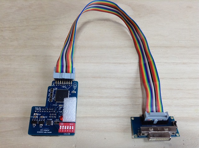


Installation must be done while the power of equipment is off.
取り付けは、必ず機器の電源を切った状態で行ってください。
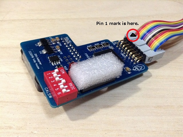
Confirm that the flat cable is connected with the adapter like this. The cable is on the upper side of the connector. If you don't connect them correctly, the Apple II GS, the adapter and/or the monitor will be damaged.
フラットケーブルがアダプタとこのように接続されていることを確認して下さい。フラットケーブルはコネクタの上側にあります。 正しく接続されていない場合、Apple II GS、アダプタ、モニタを破損します。
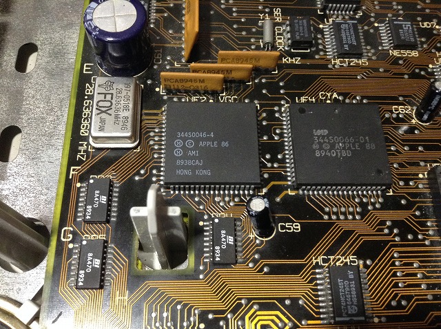
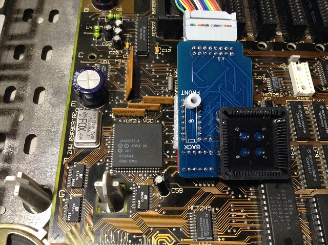
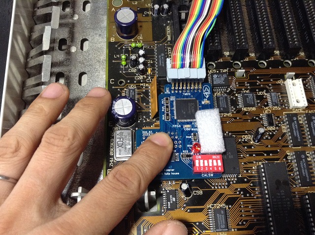
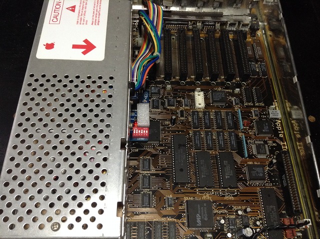
Plug the adapter on the VGC chip (UF2) on the logic board. Push the adapter and confirm that it is fixed firmly.
Don't peel the tape on the PLCC connector off. This tape enables the adapter fixed firmly.
ロジックボード上のVGCチップ (UF2) の上にアダプタを装着します。アダプターを押して、しっかりと固定されているか確認して下さい。
PLCCコネクタに貼ってあるテープを剥がさないでください。これにより、アダプタがしっかりと固定されます。
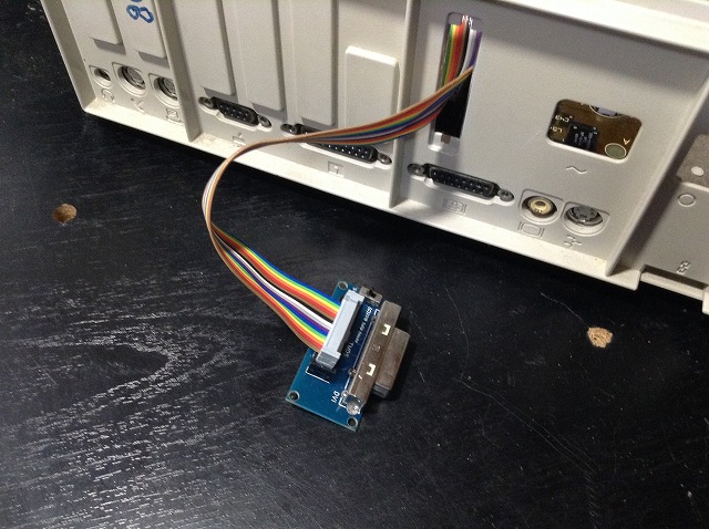
Connect the flat cable with the DVI connector mini board. And connect a DVI monitor with the DVI connector.
Never connect this adapter with a DVI output of equipment! It will damage the equipment and/or the adapter.
フラットケーブルを DVI コネクタ・ミニボードと接続します。最後に DVI モニタをその DVI コネクタと接続します。
必ず、モニタのDVI入力に接続してください。機器のDVI出力には絶対に接続しないでください。機器やアダプタが故障します。
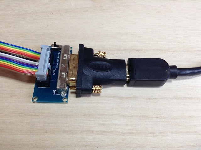
If you use a TV with an HDMI input, use a DVI - HDMI conversion adapter that is commercially available.
Never connect this adapter with an HDMI output of equipment! It will damage the equipment and/or the adapter.
必ず、テレビのHDMI入力に接続してください。機器のHDMI出力には絶対に接続しないでください。機器やアダプタが故障します。
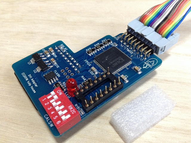
The 16 pin connector on the adapter is used to update the FPGA configuration via the game port when the new configuration is released in the future. The pins are easy to bend, so please cover them with the urethane foam.
アダプター上の16ピン・コネクタは、将来、新しい FPGA コンフィグレーションがリリースされた時に、ゲームポートに接続してアップデートするためのものです。ピンは曲がりやすいので、ウレタンフォームでカバーしておいて下さい。
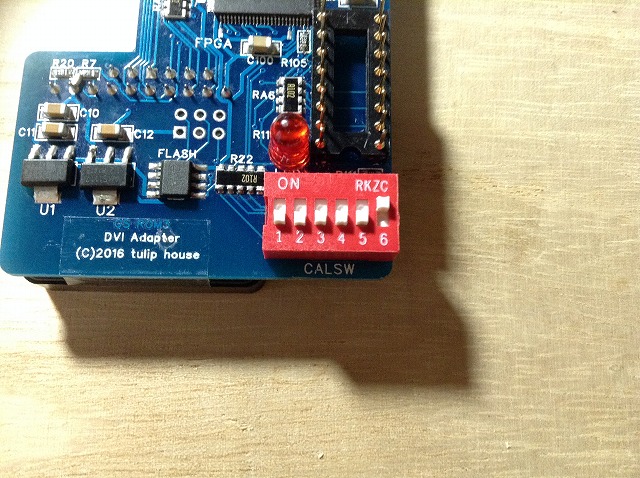
This adapter outputs TMDS signal with either 27 MHz pixel clock (720 x 480) or 25 MHz (640 x 480). Your monitor may support either of them. When the SW4 of the DIP switches is OFF, it is 27 MHz. When the SW4 is ON, it is 25 MHz. The switching should be done while the power of the Apple II GS is off.
このアダプタは、ピクセルクロック 27 MHz (720x480)、または 25 MHz (640x480) どちらかの TMDS 信号を出力します。モニタによっては、どちらかしかサポートしていないかもしれません。DIP スイッチの SW4 が OFF の時、27 MHz, ON の時、25 MHz になります。スイッチ切り替えは、Apple II GS の電源がオフの状態で行ってください。
Turn off the SW3 of the DIP switches. Change the SW1 - 2 of the DIP switches so that the screen is stable and images are displayed beautifully in both IIe compatible screen mode and GS screen mode.
After calibration, images are filtered in GS screen mode if the SW3 is ON. If you prefer filtered images, use this mode.
DIP スイッチの SW3 を OFF にして下さい。IIe コンパチブルの画面モードと GS の画面モードの両方で、画面が安定し、美しく表示されるように、DIP スイッチの SW1 - 2 を切り替えて下さい。
キャリブレーション終了後、SW3は、ONにすると、GSの画面モードでフィルタがかかるようになります。お好みにより、このモードを使用して下さい。
Boot the GS OS, and change the SW1 - 3 of the DIP switches so that the screen is stable and the stripes on the background is displayed beautifully.
GS OS を立ち上げて、DIP スイッチの SW1 - 3 を変えて、画面が安定し、バックグラウンドの縦のストライプが美しく表示されるようにします。
When the SW5 of the DIP switches is OFF, the adapter runs in auto detection mode, and the sampling frequency is selected automatically from either 16.363 MHz (GS screen mode) or 14.318 MHz (IIe compatible screen mode).
DIP スイッチの SW5 が OFF の時、アダプタは自動検出モードで動作し、サンプリング周波数が 16.363 MHz (GS 画面モード) と14.318 MHz (IIe コンパチ画面モード) に自動で切り替わります。
Since this auto detection is not perfect, you can also use the adapter in manual mode by making the SW5 of the DIP switches ON. In manual mode, you can select sampling frequency by changing the switch on the DVI connector mini board.
この自動検出は完璧ではないので、DIP スイッチの SW5 を ON にすることでマニュアルモードで使うこともできます。マニュアルモードでは、DVI コネクタ・ミニボードに付いているスイッチを変えることでサンプリング周波数を選択できます。
When the adapter is running in auto detection mode, the switch on the DVI connector mini board is used for displaying scan lines.
自動検出モードで動作している場合、DVI コネクタ・ミニボードに付いているスイッチは、スキャンラインを表示するために用いられます。
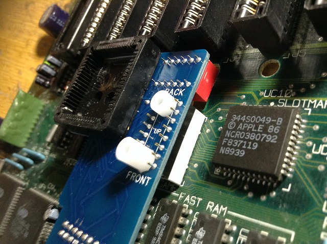
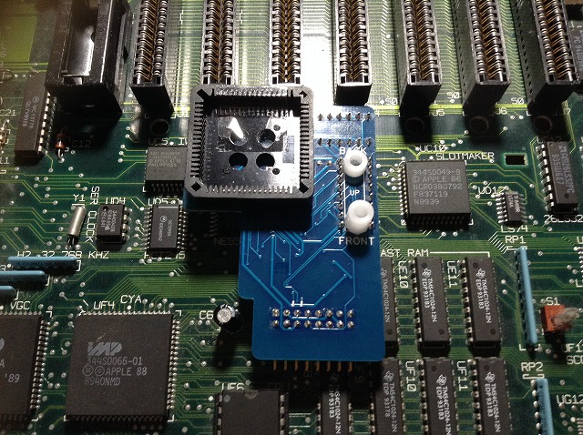
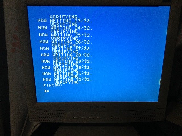
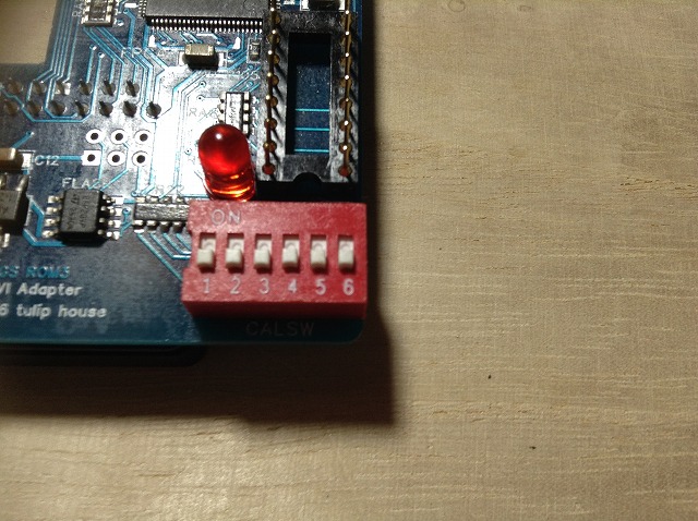

Basically you don't have to update the configuration if the DVI adapter is working correctly. But when something is wrong, try to update the configuration. You need a TV or an RGB monitor to see the progress of the update. When you are connecting the adapter with the 16 pin game port, don't connect a joystick with the 9 pin game port. It may damage the adapter. And don't push the open apple key (command key).
基本的に、DVI アダプタが動作していれば、コンフィグレーションをアップデートする必要はありません。もし正しく動作していない場合、コンフィグレーションをアップデートしてみて下さい。アップデートの進捗を見るためにテレビか RGB モニタが必要です。また、アップデートの作業中は、ジョイスティックを取り外して下さい。アダプタにダメージを与える可能性があります。また、オープン・アップル・キー(コマンドキー)を押さないようにして下さい。
George Rentovich for offering Apple II GS ROM3 logic boards.
Dagen Brock for making a display test program for Apple II GS.
Andrew Roughan for writing an article of the VGA adapter, the previous model of this DVI adapter, for Juiced.GS.
Herbert Fung and Antoine Vignau for reporting the behavior of the VGA adapter.
Atsuhiro Suzuki for offering an Apple II GS, and testing the VGA adapter.
People in Apple II community for helping me.